Lab 17 — Design Sweeps: Three Design Curves for swing / Γrms / N
Breadcrumb: Simulation labs › System & advanced › This page (advanced design sweeps). Back-of-the-envelope intro version: lab_09; upstream: lab_06, lab_08.
β: This English translation is in beta — the Traditional-Chinese original is the authoritative version.
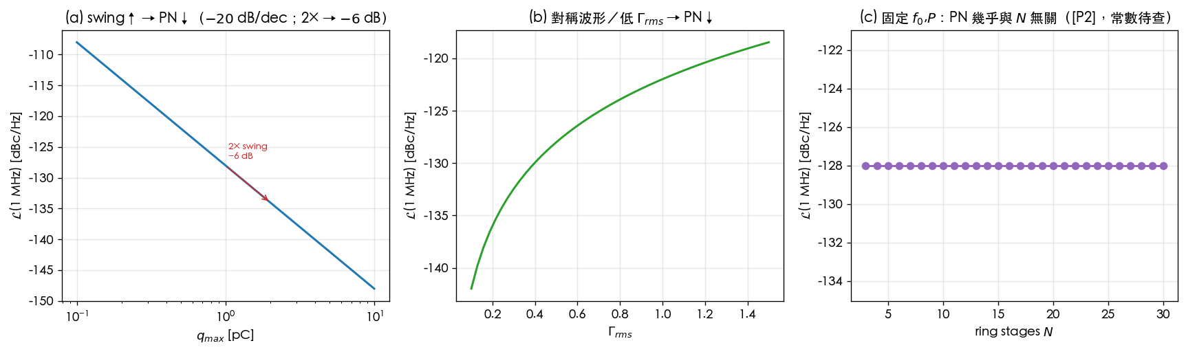
lab_09 read [P1] Eq.(21) as a scaling law by mental arithmetic. This lab actually sweeps the same equation and plots it as three curves: holding everything else fixed, sweep the node charge swing (swing), the ISF rms , and the ring stage count , and watch how the phase noise at MHz offset moves. On the plots you will see with your own eyes the " dB/decade" straight-line slope, the " swing dB" arrow, and the ring oscillator's nearly horizontal curve (the famous -independence).
Physical intuition (conclusion first): phase noise . Both knobs enter as : doubling → dB; halving → dB. The ring's is sneakier: adding stages shrinks , but the per-node shrinks and there are more noisy devices — the three roughly cancel at fixed /power, so net phase noise is almost independent of .
1. Learning objectives
- Plot [P1] Eq.(21)'s as three design curves.
- On the curve, quantify " dB/decade" and " swing dB".
- On the curve, see "symmetric waveform / low PN↓".
- On the ring curve, see where -independence comes from ([P2] Eq.(16), p.794 — v7 re-verified: ).
- Connect the curves back to lab_09 and the Chapter 06 design-insight pages.
2. Mathematical model
The starting point is again [P1] Eq.(21), p.185 ( region, fixed offset):
Expand the logarithm to expose each knob's own slope:
- Knob 1 (): → against a horizontal axis in this is a straight line with slope dB/decade; dB → dB.
- Knob 2 (): → halving → dB; this lab uses a linear horizontal axis, so the curve is the logarithmic rise of .
The ring's ([P2] Eq.(16), p.794 — v7 re-verified: the square root covers only the constant, ; the body text's at η=0.75 and App. B Eq.(55) triple-confirm this. v3 had misread it as ): adding stages moves three things at once, and the three cancel each other at fixed /power:
Substituting into :
- Conclusion: under this toy scaling the net effect → phase noise is independent of ([P2]'s signature result).
- Dimension check: → the bracket is dimensionless (before taking ), legitimate ✓; is dimensionless throughout ✓.
Numbers for this lab: evaluated at MHz, A²/Hz; the baseline pC, gives dBc/Hz.
3. Block diagram
4. Core Python code
simulations/lab_17_design_sweep.py uses a shared L_dbc to evaluate [P1] Eq.(21) in dBc/Hz,
then sweeps one curve per knob:
import numpy as np


def L_dbc(Grms, qmax, in2_df, dw):
    return 10 * np.log10(Grms ** 2 / qmax ** 2 * in2_df / (4 * dw ** 2))


dw = 2 * np.pi * 1e6        # evaluate at 1 MHz offset
in2_df = 1e-22

# (a) sweep q_max: 0.1 pC .. 10 pC  -> slope -20 dB/decade, 2x -> -6 dB
q = np.logspace(-13, -11, 50)
L_q = L_dbc(0.5, q, in2_df, dw)                # baseline qmax=1pC -> -128 dBc/Hz

# (b) sweep Gamma_rms: low Grms -> lower PN
g = np.linspace(0.1, 1.5, 50)
L_g = L_dbc(g, 1e-12, in2_df, dw)

# (c) ring N: Gamma_rms ~ N^-3/2, per-node qmax ~ 1/N, more noisy devices ~ N
N = np.arange(3, 31)
Grms_N = 0.5 * (5.0 / N) ** 1.5                # scaling (illustrative; [P2])
qmax_N = 1e-12 * (5.0 / N)                      # lower per-node swing as N grows
noise_N = in2_df * (N / 5.0)                    # more noisy devices
L_N = 10 * np.log10(Grms_N ** 2 / qmax_N ** 2 * noise_N / (4 * dw ** 2))
print(round(L_N[0], 1), round(L_N[-1], 1))
# -> -128.0 -128.0  (essentially flat for all N: the famous N-independence)
L_dbcvs lab_08: lab_08 integrates the measured into jitter; here we go the other way, using Eq.(21) to generate and then sweep the knobs. The two pages are inverse operations of each other (same note as in lab_09).- The three scalings in (c) are illustrative: the constant in and the exponents for per-node and device count are toy assumptions, meant to draw concretely "why roughly cancels".
5. Full script path
simulations/lab_17_design_sweep.py (main() draws the three subplots; L_dbc wraps [P1] Eq.(21) in dBc/Hz;
(c) uses the toy scaling , , ).
Re-run: python scripts/run_all_sims.py.
Note: this page's filename is
lab_17_design_tradeoffs.md(aligned with the sidebar naming convention); the corresponding script islab_17_design_sweep.py, and the figure file isdesign_tradeoff_sweeps.png.
6. Parameter table
| Parameter | Symbol | Value / sweep range | Role |
|---|---|---|---|
| Offset (evaluation point) | MHz | Fixed | |
| Current noise PSD | A²/Hz | Fixed (baseline); varies with in (c) | |
| Maximum charge swing | (a) – pC; baseline pC | Knob 1 | |
| ISF rms | (b) –; baseline | Knob 2 | |
| Ring stage count | (c) –; baseline | Knob 3 | |
| Baseline phase noise | dBc/Hz | From Eq.(21) ( pC, ) |
7. Unit table
| Quantity | Symbol | Unit |
|---|---|---|
| Maximum charge swing | C | |
| ISF rms | Dimensionless | |
| Ring stage count | Dimensionless | |
| Offset frequency | Hz, rad/s | |
| Phase noise | dBc/Hz | |
| Current noise PSD | A²/Hz |
8. Simulation figure
9. How to read the figure
- (a) swing sweep (blue): on a log horizontal axis, (0.1–10 pC) vs is a straight line with slope dB/decade — as goes from 0.1 → 10 pC (two decades), drops from → dBc/Hz, exactly dB. The red arrow marks " swing dB" ( pC, dBc/Hz). Mnemonic: double the swing, gain 6 dB of phase noise.
- (b) sweep (green): linear horizontal axis, a logarithmic curve const — smaller means lower phase noise, with the steepest descent at the small- end (halving from 0.5 to 0.25 → dB). This is the payoff of "symmetric waveform / low sensitivity".
- (c) ring sweep (purple): a nearly perfectly horizontal line ( dBc/Hz, independent of ). Not a coincidence — it is the computed in Section 2: more stages shrink (good), but also shrinks and there are more devices (bad); the three cancel at fixed /power. Adding ring stages does not buy you phase noise for free ([P2]).
- Putting it together: (a)(b) are the "knobs that truly earn dB" (raise the swing, suppress ); (c) is the "looks tunable, actually cancels" knob — choose based on , power, area, and phase-count requirements, not for phase noise.
10. Corresponding paper equations/figures
- Main scaling: [P1] Eq.(21), p.185, .
- Parseval / : [P1] Eq.(20), p.185.
- Ring scaling: [P2] Eq.(16), p.794 (v7 re-verified: the square root covers only the constant, ; the body text's at η=0.75 and App. B Eq.(55) triple-confirm this. v3 had misread it as ).
- Ring frequency: [P2] Eq.(15), p.794, .
- Ring white-noise FOM / -independence: [P2], p.795, (the prefactor of [P2] Eq.(23), p.796 is ( being the stage-delay proportionality constant of Eq.14, ); enters only through . v2 mistakenly changed this to and mislabeled it "verified verbatim"; v3 corrected it against the original PDF p.796).
11. Limitations and approximations
- Toy scaling, not transistor-level: (a)(b) assume "turn one knob only, everything else perfectly fixed"; in real circuits , , , power, area, and are coupled and cannot be tuned in isolation.
- The three exponents in ring (c) are illustrative: , ,
are toy assumptions to demonstrate the cancellation; the exact constants are marked
TODO: manual verification needed from [P2] page 794–796. Changing also changes (unless is shrunk), which this figure does not show simultaneously. - region only, fixed offset: evaluated at MHz; close-in is dominated by and the lower integration limit, where these three plots do not apply (see lab_07).
- Single white noise source: ignores multiple sources, cyclostationarity (, lab_14), and AM–PM.
- Factor-of-2: uses Eq.(21)'s convention; the factor-of-2 SSB-bookkeeping difference does not affect any relative (dB) slope.
- Jitter inference: ( dB phase noise = jitter halved) requires a fixed integration range and shape; see lab_08, lab_09.
Key takeaways
- curve: dB/decade; swing dB (baseline → dBc/Hz).
- curve: , halving dB; symmetric waveforms / low sensitivity pay off.
- Ring curve: nearly horizontal — , phase noise is independent of ([P2] Eq.(16), p.794, v7 re-verified: ).
- Baseline: pC, , , MHz dBc/Hz.
Further reading
- Back-of-the-envelope design trade-offs: lab_09_design_tradeoffs
- Swing / design: tank_swing
- Waveform slope and : waveform_slope
- Symmetry kills : symmetry
- Upstream simulations: lab_06_white_noise_phase_noise, lab_08_jitter_integration
- Applied to design/theory: the three scaling curves (swing / / -independence) land on the LC vs ring topology decision → lc_vs_ring