從 ISF 看 LC vs ring oscillator
先備 :tank_swing (L ∝ Γ r m s 2 / q m a x 2 \mathcal{L}\propto\Gamma_{rms}^2/q_{max}^2 L ∝ Γ r m s 2 / q ma x 2 tank_Q_and_energy_restoration (LC「高 Q Q Q rms_isf (Γ r m s \Gamma_{rms} Γ r m s N − 3 / 2 N^{-3/2} N − 3/2 接下來 :serdes_clocking_connection 、varactor_tuning_supply_pushing
這頁把 ISF 當成一支統一的尺 ,逐項量 LC 與 ring 兩種振盪器的差別。重點不是「誰比較好」
(各有用途),而是ISF 框架讓我們看見什麼、看不見什麼 。我們會先建一個誠實標明的 toy model,
再用 [P1] / [P2] 的公式把差異量化。
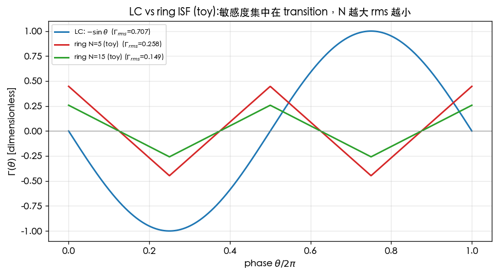
物理直覺(先講結論) :LC 像一個沉重的鐘擺 ——能量大半儲在 tank(L L L C C C − sin -\sin − sin 接力傳球的閘 ——沒有能量儲存元件,每一級都在切換、每一級都在漏雜訊,波形接近方波、
ISF 集中在 transition、相位敏感度尖銳。LC 用「儲能 + 高 Q Q Q
Toy model 假設(誠實標明)
以下是 pedagogical toy model(教學玩具模型,非 transistor-level) 。它抓住定性差異,
但不是任何真實電路的量測。
LC :理想 sinusoidal state(正弦狀態),V ( θ ) = cos θ V(\theta)=\cos\theta V ( θ ) = cos θ Γ L C ( θ ) = − sin θ \Gamma_{LC}(\theta)=-\sin\theta Γ L C ( θ ) = − sin θ ring :N N N ∼ 1 / N \sim1/\sqrt{N} ∼ 1/ N σ Δ t = σ e d g e Δ N \sigma_{\Delta t}=\sigma_{edge}\sqrt{\Delta N} σ Δ t = σ e d g e Δ N 完整 script:simulations/lab_02_lc_toy_model.py、simulations/lab_03_ring_toy_model.py。
逐項比較表
面向 LC oscillator Ring oscillator ISF 怎麼解釋 波形 接近正弦 接近方波(rail-to-rail) 決定 ISF 形狀(平滑 vs 集中於 transition) ISF 形狀 − sin θ -\sin\theta − sin θ 三角形,尖、集中於 transition 見 [P1] Fig. 7 amplitude restoration tank + 非線性 g m g_m g m 每級飽和到 rail,強 restoration 振幅擾動衰減→只追蹤相位(claim C2) transition slope 中等(正弦過零斜率) 陡(快速切換) 陡邊緣→低 threshold jitter、Γ r m s \Gamma_{rms} Γ r m s 儲能(tank energy) 高(L L L C C C 幾乎無儲能 高儲能→大 q m a x q_{max} q ma x noisy device 數目 少(1~2 個主動 device) 多(N N N noise 源越多、貢獻越多(但每級 swing 較小) 相位敏感度分佈 分散整個週期 集中在 transition 視窗 Γ e f f = Γ ⋅ α \Gamma_{eff}=\Gamma\cdot\alpha Γ e f f = Γ ⋅ α Γ r m s \Gamma_{rms} Γ r m s 0.5 0.5 0.5 − sin -\sin − sin Γ r m s ∝ N − 3 / 2 \Gamma_{rms}\propto N^{-3/2} Γ r m s ∝ N − 3/2 [P2] Eq.(16) jitter accumulation 慢(高 Q Q Q 快(無 reference,random walk) σ Δ t = κ Δ t \sigma_{\Delta t}=\kappa\sqrt{\Delta t} σ Δ t = κ Δ t 典型 phase noise 低(好 10~30 dB) 高 ∝ Γ r m s 2 / q m a x 2 \propto\Gamma_{rms}^2/q_{max}^2 ∝ Γ r m s 2 / q ma x 2 面積/可調性/多相位 大(spiral inductor)、調諧範圍窄 小、寬調諧、天生多相位輸出 (非 ISF 量,但設計常衡量)
第 1 步:Γ r m s \Gamma_{rms} Γ r m s
理想 LC Γ L C ( θ ) = − sin θ \Gamma_{LC}(\theta)=-\sin\theta Γ L C ( θ ) = − sin θ
Γ r m s , L C = 1 2 π ∫ 0 2 π sin 2 θ d θ = 1 2 ≈ 0.707 \Gamma_{rms,LC}=\sqrt{\frac{1}{2\pi}\int_0^{2\pi}\sin^2\theta\,d\theta}=\sqrt{\frac{1}{2}}\approx0.707 Γ r m s , L C = 2 π 1 ∫ 0 2 π sin 2 θ d θ = 2 1 ≈ 0.707 注意 normalization 慣例:本站用 ∑ n = 0 ∞ c n 2 = 2 Γ r m s 2 \sum_{n=0}^{\infty}c_n^2=2\Gamma_{rms}^2 ∑ n = 0 ∞ c n 2 = 2 Γ r m s 2 − sin θ -\sin\theta − sin θ c 1 = 1 c_1=1 c 1 = 1 ∑ c n 2 = 1 = 2 Γ r m s 2 ⇒ Γ r m s = 1 / 2 ≈ 0.707 \sum c_n^2=1=2\Gamma_{rms}^2\Rightarrow\Gamma_{rms}=1/\sqrt2\approx0.707 ∑ c n 2 = 1 = 2 Γ r m s 2 ⇒ Γ r m s = 1/ 2 ≈ 0.707 Γ r m s = 0.5 \Gamma_{rms}=0.5 Γ r m s = 0.5 算具體 dBc/Hz 時一律用 canonical Γ r m s = 0.5 \Gamma_{rms}=0.5 Γ r m s = 0.5 (見 notation 與 rms_isf )。
下圖把 LC 的 − sin -\sin − sin N = 5 , 15 N=5,15 N = 5 , 15 N N N 變矮
(峰值 ∼ 1 / N \sim1/\sqrt N ∼ 1/ N 數目變多 (N N N Γ r m s \Gamma_{rms} Γ r m s N N N
第 2 步:ring 的三條 [P2] 公式(已對照 PDF 核實)
(a) ring 頻率 ([P2] Eq.(15), p.794):
f 0 = 1 2 N τ D f_0=\frac{1}{2N\,\tau_D} f 0 = 2 N τ D 1
τ D \tau_D τ D 兩圈 才完成一個完整週期(單端 ring 需奇數級反相)。單位檢查 :1 / ( N ⋅ [ s ] ) = [ Hz ] 1/(N\cdot[\text{s}])=[\text{Hz}] 1/ ( N ⋅ [ s ]) = [ Hz ] 設計含意 :固定 f 0 f_0 f 0 N N N τ D \tau_D τ D
(b) ring Γ r m s \Gamma_{rms} Γ r m s ([P2] Eq.(16), p.794(v7 已重核:根號只蓋常數,Γrms ∝ N^-1.5;正文 4/N^1.5@η=0.75 與 App.B Eq.(55) 三重驗證。v3 曾誤讀為 N^-0.75)):
Γ r m s = 2 π 2 3 η 3 1 N 1.5 ⇒ Γ r m s ∝ N − 3 / 2 ( Γ r m s 2 ∝ N − 3 ) \Gamma_{rms}=\sqrt{\frac{2\pi^2}{3\eta^3}}\;\dfrac{1}{N^{1.5}}\;\Rightarrow\;\Gamma_{rms}\propto N^{-3/2}\quad(\Gamma_{rms}^2\propto N^{-3}) Γ r m s = 3 η 3 2 π 2 N 1.5 1 ⇒ Γ r m s ∝ N − 3/2 ( Γ r m s 2 ∝ N − 3 )
直覺:級數越多,每個 transition 佔週期的「敏感視窗」越窄、單級 ISF 峰值越矮,rms 隨之下降。
根號範圍註記 :印刷公式的根號只蓋常數 2 π 2 / ( 3 η 3 ) 2\pi^2/(3\eta^3) 2 π 2 / ( 3 η 3 ) 1 / N 1.5 1/N^{1.5} 1/ N 1.5 Γ r m s ∝ N − 3 / 2 \Gamma_{rms}\propto N^{-3/2} Γ r m s ∝ N − 3/2 η = 0.75 \eta=0.75 η = 0.75 2 π 2 / ( 3 ⋅ 0.75 3 ) ≈ 3.95 \sqrt{2\pi^2/(3\cdot0.75^3)}\approx3.95 2 π 2 / ( 3 ⋅ 0.7 5 3 ) ≈ 3.95 Γ r m s ≈ 4 / N 1.5 \Gamma_{rms}\approx4/N^{1.5} Γ r m s ≈ 4/ N 1.5 1 / N 1.5 1/N^{1.5} 1/ N 1.5 Γ r m s \Gamma_{rms} Γ r m s paper_002 deep-dive 。
(c) ring 白噪 phase noise FOM ([P2] Eq.(23), p.796,已對照原始 PDF 核實 ✓):
L { Δ f } = 8 3 η ⋅ k T P ⋅ V D D V c h a r ⋅ ( f 0 Δ f ) 2 \mathcal{L}\{\Delta f\}=\frac{8}{3\eta}\cdot\frac{kT}{P}\cdot\frac{V_{DD}}{V_{char}}\cdot\left(\frac{f_0}{\Delta f}\right)^2 L { Δ f } = 3 η 8 ⋅ P k T ⋅ V c ha r V D D ⋅ ( Δ f f 0 ) 2
前置係數是 8 / ( 3 η ) 8/(3\eta) 8/ ( 3 η ) η \eta η η ≈ 1 \eta\approx1 η ≈ 1 γ \gamma γ 2 / 3 2/3 2/3 僅透過 V c h a r = Δ V / γ V_{char}=\Delta V/\gamma V c ha r = Δ V / γ P P P P = 2 η N V D D q m a x f 0 P=2\eta N V_{DD}q_{max}f_0 P = 2 η N V D D q ma x f 0 注意 γ \gamma γ η \eta η
單位檢查 :[ J ] [ W ] ⋅ ( 無因次 ) 2 = [ J ] [ J/s ] = [ s ] \dfrac{[\text{J}]}{[\text{W}]}\cdot(\text{無因次})^2=\dfrac{[\text{J}]}{[\text{J/s}]}=[\text{s}] [ W ] [ J ] ⋅ ( 無因次 ) 2 = [ J/s ] [ J ] = [ s ] 10 log 10 10\log_{10} 10 log 10 V T = 0 V_T=0 V T = 0 L > 16 γ 3 η k T P ( f 0 / Δ f ) 2 \mathcal{L}>\frac{16\gamma}{3\eta}\frac{kT}{P}(f_0/\Delta f)^2 L > 3 η 16 γ P k T ( f 0 /Δ f ) 2 8 / ( 3 η ) 8/(3\eta) 8/ ( 3 η ) η \eta η ≈ 1 \approx1 ≈ 1 γ \gamma γ V c h a r = Δ V / γ V_{char}=\Delta V/\gamma V c ha r = Δ V / γ 8 / ( 3 γ ) 8/(3\gamma) 8/ ( 3 γ )
(d) N-independence 結論 (claim C7,已核實):
關鍵事實:[P2] Eq.(23) 的 FOM 裡完全沒有 N N N ——固定 f 0 f_0 f 0 P P P N N N N N N Γ r m s \Gamma_{rms} Γ r m s q m a x q_{max} q ma x f 0 f_0 f 0 N N N P P P f 0 f_0 f 0 N N N paper_002 deep-dive 。
結論 :固定中心頻率與功耗下,加級數不會 改善 ring 的 phase noise/jitter——[P2] 的招牌反直覺結果。設計含意 :選 N N N f 0 f_0 f 0 不是 為了 phase noise。
第 2b 步:差動 ring——N-independence 失落的另一半([P2] Eq.(31)–(35), p.796,已核實 ✓)
上面的 N-independence 只講了一半的故事 :它是 single-ended CMOS ring 的結論。
[P2] Sec. V-B(p.796)對 differential(差動) MOS ring(電阻負載 R L R_L R L phase noise 公式裡明含一個因子 N N N 。以下五條公式均已對照
[P2] 原始 PDF p.796 逐字核實(渲染頁截圖比對)。
(a) 功率記帳從「動態」變「靜態」 ([P2] Eq.(31), p.796):
P = N I t a i l V D D P=N\,I_{tail}\,V_{DD} P = N I t ai l V D D
差動對由 tail current source(尾電流源)恆流偏置:不管有沒有在切換 ,每級都持續從
V D D V_{DD} V D D I t a i l I_{tail} I t ai l N N N N N N
單位檢查 :( 無因次 ) ⋅ [ A ] ⋅ [ V ] = [ W ] (\text{無因次})\cdot[\text{A}]\cdot[\text{V}]=[\text{W}] ( 無因次 ) ⋅ [ A ] ⋅ [ V ] = [ W ] 對照 single-ended 的 Eq.(21) P = 2 η N V D D q m a x f 0 P=2\eta N V_{DD}q_{max}f_0 P = 2 η N V D D q ma x f 0 q m a x q_{max} q ma x 動態 功耗,功率自動綁著 f 0 f_0 f 0 靜態 功耗與 f 0 f_0 f 0
(b) 頻率=tail 電流對節點電荷 slew ([P2] Eq.(32), p.796):
f 0 = 1 2 N t D ≈ 1 2 η N t r ≈ I t a i l 2 η N q m a x f_0=\frac{1}{2Nt_D}\approx\frac{1}{2\eta N t_r}\approx\frac{I_{tail}}{2\eta N q_{max}} f 0 = 2 N t D 1 ≈ 2 η N t r 1 ≈ 2 η N q ma x I t ai l
最後一步的物理:每級 transition 是 tail current 對節點電荷 q m a x q_{max} q ma x t r ≈ q m a x / I t a i l t_r\approx q_{max}/I_{tail} t r ≈ q ma x / I t ai l η \eta η ≈ 1 \approx1 ≈ 1
單位檢查 :[ A ] / ( [ C ] ) = [ A/(A⋅s) ] = 1 / s = [ Hz ] [\text{A}]/([\text{C}])=[\text{A/(A·s)}]=1/\text{s}=[\text{Hz}] [ A ] / ([ C ]) = [ A/(A⋅s) ] = 1/ s = [ Hz ] factor-2 flag :1 / ( 2 N t D ) 1/(2Nt_D) 1/ ( 2 N t D ) 無關 。
(c) 固定 P P P f 0 f_0 f 0 N N N
由 Eq.(31) 反解:I t a i l = P / ( N V D D ) ∝ 1 / N I_{tail}=P/(N V_{DD})\propto 1/N I t ai l = P / ( N V D D ) ∝ 1/ N
代入 Eq.(32):q m a x = I t a i l / ( 2 η N f 0 ) ∝ 1 / N 2 q_{max}=I_{tail}/(2\eta N f_0)\propto 1/N^2 q ma x = I t ai l / ( 2 η N f 0 ) ∝ 1/ N 2 1 / N 1/N 1/ N 又 要
在更短的級延遲內完成 transition(再一個 1 / N 1/N 1/ N q m a x q_{max} q ma x by a factor of 1 / N 2 1/N^2 1/ N 2 ."
對照 single-ended:Eq.(21) 在固定 P P P f 0 f_0 f 0 q m a x ∝ 1 / N q_{max}\propto1/N q ma x ∝ 1/ N f 0 f_0 f 0
(d) 每個節點的雜訊 ([P2] Eq.(33), p.796):
i n 2 ‾ Δ f = ( i n 2 ‾ Δ f ) N + ( i n 2 ‾ Δ f ) L o a d = 4 k T I t a i l ( 1 V c h a r + 1 R L I t a i l ) \frac{\overline{i_n^2}}{\Delta f}=\left(\frac{\overline{i_n^2}}{\Delta f}\right)_{N}+\left(\frac{\overline{i_n^2}}{\Delta f}\right)_{Load}=4kT\,I_{tail}\left(\frac{1}{V_{char}}+\frac{1}{R_L I_{tail}}\right) Δ f i n 2 = ( Δ f i n 2 ) N + ( Δ f i n 2 ) L o a d = 4 k T I t ai l ( V c ha r 1 + R L I t ai l 1 )
兩份來源:差動電晶體 (下標 N N N 負載電阻 R L R_L R L V c h a r V_{char} V c ha r ( V G S − V T ) / γ (V_{GS}-V_T)/\gamma ( V GS − V T ) / γ E c L / γ E_cL/\gamma E c L / γ
單位檢查 :4 k T I t a i l / V c h a r = [ J ] [ A ] / [ V ] 4kT I_{tail}/V_{char}=[\text{J}][\text{A}]/[\text{V}] 4 k T I t ai l / V c ha r = [ J ] [ A ] / [ V ] [ J ] = [ V⋅A⋅s ] [\text{J}]=[\text{V·A·s}] [ J ] = [ V⋅A⋅s ] = [ V⋅A⋅s⋅A/V ] = [ A 2 ⋅s ] = [ A 2 / Hz ] =[\text{V·A·s·A/V}]=[\text{A}^2\text{·s}]=[\text{A}^2/\text{Hz}] = [ V⋅A⋅s⋅A/V ] = [ A 2 ⋅s ] = [ A 2 / Hz ] 2 N 2N 2 N 兩個 輸出節點,全環共 2 N 2N 2 N 2 N 2N 2 N 2 N 2N 2 N 節點計數 ,不是 SSB 慣例的 2。tail 源哪去了?同頁原文:"Surprisingly, tail-current source noise in the vicinity of f 0 f_0 f 0 低頻 雜訊(走 symmetry/c 0 c_0 c 0 symmetry )與偶次諧波附近 的雜訊(可用串聯電感
/並聯電容壓制),所以白噪記帳只算差動管+負載兩份。
(e) 收斂:差動 ring 的 phase noise 與 jitter 下限 ([P2] Eq.(34)/(35), p.796):
L m i n { Δ f } = 8 3 η ⋅ N ⋅ k T P ⋅ ( V D D V c h a r + V D D R L I t a i l ) ⋅ f 0 2 Δ f 2 \mathcal{L}_{min}\{\Delta f\}=\frac{8}{3\eta}\cdot N\cdot\frac{kT}{P}\cdot\left(\frac{V_{DD}}{V_{char}}+\frac{V_{DD}}{R_L I_{tail}}\right)\cdot\frac{f_0^2}{\Delta f^2} L min { Δ f } = 3 η 8 ⋅ N ⋅ P k T ⋅ ( V c ha r V D D + R L I t ai l V D D ) ⋅ Δ f 2 f 0 2 κ m i n = 8 3 η ⋅ N ⋅ k T P ⋅ ( V D D V c h a r + V D D R L I t a i l ) \kappa_{min}=\sqrt{\frac{8}{3\eta}}\cdot\sqrt{N\cdot\frac{kT}{P}\cdot\left(\frac{V_{DD}}{V_{char}}+\frac{V_{DD}}{R_L I_{tail}}\right)} κ min = 3 η 8 ⋅ N ⋅ P k T ⋅ ( V c ha r V D D + R L I t ai l V D D ) (L \mathcal{L} L L { Δ f } L\{\Delta f\} L { Δ f } V c h a r V_{char} V c ha r 同兩式 ,V c h a r = 4 k T / q e V_{char}=4kT/q_e V c ha r = 4 k T / q e
與 single-ended 的 Eq.(23) 相比只差兩處 :多了明含的 N N N V D D / ( R L I t a i l ) V_{DD}/(R_L I_{tail}) V D D / ( R L I t ai l ) N N N L ∝ ( 源數 ) ⋅ Γ r m s 2 ⋅ S i / q m a x 2 \mathcal{L}\propto(\text{源數})\cdot\Gamma_{rms}^2\cdot S_i/q_{max}^2 L ∝ ( 源數 ) ⋅ Γ r m s 2 ⋅ S i / q ma x 2 P P P f 0 f_0 f 0 R L I t a i l R_L I_{tail} R L I t ai l
因子 single-ended(Eq.23 之路) differential(Eq.34 之路) noise 源數 × N \times N × N × 2 N ∝ N \times 2N\propto N × 2 N ∝ N Γ r m s 2 \Gamma_{rms}^2 Γ r m s 2 ∝ N − 3 \propto N^{-3} ∝ N − 3 ∝ N − 3 \propto N^{-3} ∝ N − 3 每源 S i S_i S i ∝ N 0 \propto N^{0} ∝ N 0 P , f 0 P,f_0 P , f 0 W W W ∝ I t a i l ∝ N − 1 \propto I_{tail}\propto N^{-1} ∝ I t ai l ∝ N − 1 1 / q m a x 2 1/q_{max}^2 1/ q ma x 2 ∝ N 2 \propto N^{2} ∝ N 2 q m a x ∝ 1 / N q_{max}\propto1/N q ma x ∝ 1/ N ∝ N 4 \propto N^{4} ∝ N 4 q m a x ∝ 1 / N 2 q_{max}\propto1/N^2 q ma x ∝ 1/ N 2 乘積 N 1 − 3 + 0 + 2 = N 0 N^{1-3+0+2}=N^{0} N 1 − 3 + 0 + 2 = N 0 N 1 − 3 − 1 + 4 = N + 1 N^{1-3-1+4}=N^{+1} N 1 − 3 − 1 + 4 = N + 1
single-ended 恰好全消(N 0 N^0 N 0 N N N q m a x ∝ 1 / N 2 q_{max}\propto1/N^2 q ma x ∝ 1/ N 2 N + 1 N^{+1} N + 1 N N N
[P2] 自己的結論句(pp.796–797,逐字) :"Note that, in contrast with the single-ended ring
oscillator, a differential oscillator does exhibit a phase noise and jitter dependency on the
number of stages, with the phase noise degrading as the number of stages increases for a given
frequency and power dissipation. This result may be understood as a consequence of the necessary
reduction in the charge swing that is required to accommodate a constant frequency of oscillation
at a fixed power level as N N N 隨 N N N ;禍首是被迫縮小的
charge swing(q m a x ∝ 1 / N 2 q_{max}\propto1/N^2 q ma x ∝ 1/ N 2
慣例 flag(每次出現 2 或 4 都要交代) :Eq.(34) 的前置係數 8 / ( 3 η ) 8/(3\eta) 8/ ( 3 η ) SSB 記帳 (與 [P1] Eq.(21) 分母的 4 同一慣例家族;換成時域 / 2 /2 /2 + 3 +3 + 3 − 148 -148 − 148 / 4 /4 /4 − 145 -145 − 145 / 2 /2 /2 white_noise_to_phase_noise )。下面例 3 的
Δ L \Delta\mathcal{L} Δ L L \mathcal{L} L 相減 ,慣例因子相消——兩種慣例答案相同 。
例 3(差動 ring:N = 4 N=4 N = 4 N = 12 N=12 N = 12 P P P f 0 f_0 f 0 Δ L \Delta\mathcal{L} Δ L
取 f 0 = 5 f_0=5 f 0 = 5 Δ f = 1 \Delta f=1 Δ f = 1 k T = 4.0 × 10 − 21 kT=4.0\times10^{-21} k T = 4.0 × 1 0 − 21 P = 1 P=1 P = 1 η ≈ 1 \eta\approx1 η ≈ 1 V D D / V c h a r = 3 V_{DD}/V_{char}=3 V D D / V c ha r = 3 R L I t a i l = V D D / 2 R_L I_{tail}=V_{DD}/2 R L I t ai l = V D D /2 ⇒ V D D / ( R L I t a i l ) = 2 \Rightarrow V_{DD}/(R_L I_{tail})=2 ⇒ V D D / ( R L I t ai l ) = 2 = 3 + 2 = 5 =3+2=5 = 3 + 2 = 5 R L ∝ N R_L\propto N R L ∝ N N N N
逐步代入(帶單位) :
( f 0 Δ f ) 2 = ( 5000 ) 2 = 2.5 × 10 7 , k T P = 4.0 × 10 − 21 J 1 × 10 − 3 W = 4.0 × 10 − 18 s , N = 4 : L m i n = 10 log 10 ( 8 3 ⋅ 4 ⋅ ( 4.0 × 10 − 18 ) ⋅ 5 ⋅ ( 2.5 × 10 7 ) ) = 10 log 10 ( 5.33 × 10 − 9 ) = − 82.7 dBc/Hz , N = 12 : L m i n = 10 log 10 ( 8 3 ⋅ 12 ⋅ ( 4.0 × 10 − 18 ) ⋅ 5 ⋅ ( 2.5 × 10 7 ) ) = 10 log 10 ( 1.60 × 10 − 8 ) = − 78.0 dBc/Hz , Δ L = 10 log 10 12 4 = 10 log 10 3 = + 4.77 dB . \begin{aligned}
\left(\frac{f_0}{\Delta f}\right)^2&=(5000)^2=2.5\times10^{7},\qquad
\frac{kT}{P}=\frac{4.0\times10^{-21}\ \text{J}}{1\times10^{-3}\ \text{W}}=4.0\times10^{-18}\ \text{s},\\[4pt]
N=4:\ \mathcal{L}_{min}&=10\log_{10}\!\Big(\tfrac{8}{3}\cdot4\cdot(4.0\times10^{-18})\cdot5\cdot(2.5\times10^{7})\Big)
=10\log_{10}(5.33\times10^{-9})=-82.7\ \text{dBc/Hz},\\[4pt]
N=12:\ \mathcal{L}_{min}&=10\log_{10}\!\Big(\tfrac{8}{3}\cdot12\cdot(4.0\times10^{-18})\cdot5\cdot(2.5\times10^{7})\Big)
=10\log_{10}(1.60\times10^{-8})=-78.0\ \text{dBc/Hz},\\[4pt]
\Delta\mathcal{L}&=10\log_{10}\frac{12}{4}=10\log_{10}3=+4.77\ \text{dB}.
\end{aligned} ( Δ f f 0 ) 2 N = 4 : L min N = 12 : L min Δ L = ( 5000 ) 2 = 2.5 × 1 0 7 , P k T = 1 × 1 0 − 3 W 4.0 × 1 0 − 21 J = 4.0 × 1 0 − 18 s , = 10 log 10 ( 3 8 ⋅ 4 ⋅ ( 4.0 × 1 0 − 18 ) ⋅ 5 ⋅ ( 2.5 × 1 0 7 ) ) = 10 log 10 ( 5.33 × 1 0 − 9 ) = − 82.7 dBc/Hz , = 10 log 10 ( 3 8 ⋅ 12 ⋅ ( 4.0 × 1 0 − 18 ) ⋅ 5 ⋅ ( 2.5 × 1 0 7 ) ) = 10 log 10 ( 1.60 × 1 0 − 8 ) = − 78.0 dBc/Hz , = 10 log 10 4 12 = 10 log 10 3 = + 4.77 dB .
結果 :級數 4→12(× 3 \times3 × 3 − 82.7 -82.7 − 82.7 − 78.0 -78.0 − 78.0 + 4.77 +4.77 + 4.77 P P P f 0 f_0 f 0 Δ L = 10 log 10 ( N 2 / N 1 ) \Delta\mathcal{L}=10\log_{10}(N_2/N_1) Δ L = 10 log 10 ( N 2 / N 1 ) κ m i n ∝ N \kappa_{min}\propto\sqrt{N} κ min ∝ N N × 3 N\times3 N × 3 κ × 3 ≈ 1.732 \kappa\times\sqrt3\approx1.732 κ × 3 ≈ 1.732 交叉檢查(對後文例 1 的 single-ended 值) :差動 N = 4 N=4 N = 4 − 82.7 -82.7 − 82.7 − 91.0 -91.0 − 91.0 3 → 5 3\to5 3 → 5 10 log 10 ( 5 / 3 ) = 2.2 10\log_{10}(5/3)=2.2 10 log 10 ( 5/3 ) = 2.2 × N \times N × N 10 log 10 4 = 6.0 10\log_{10}4=6.0 10 log 10 4 = 6.0 − 91.0 + 2.2 + 6.0 = − 82.8 ≈ − 82.7 -91.0+2.2+6.0=-82.8\approx-82.7 − 91.0 + 2.2 + 6.0 = − 82.8 ≈ − 82.7 Dimension check :同 Eq.(23):[ J ] [ W ] ⋅ ( 無因次 ) ⋅ ( 無因次 ) 2 = [ s ] \dfrac{[\text{J}]}{[\text{W}]}\cdot(\text{無因次})\cdot(\text{無因次})^2=[\text{s}] [ W ] [ J ] ⋅ ( 無因次 ) ⋅ ( 無因次 ) 2 = [ s ] 10 log 10 10\log_{10} 10 log 10 Python 驗證 :
import numpy as np
def L_ring_diff ( N , kT , P , f0 , df , eta = 1.0 , vdd_vchar = 3.0 , vdd_swing = 2.0 ) :
return 10 * np . log10 ( 8 / ( 3 * eta ) * N * ( kT / P ) * ( vdd_vchar + vdd_swing ) * ( f0 / df ) ** 2 )
L4 = L_ring_diff ( 4 , 4.0e-21 , 1e-3 , 5e9 , 1e6 )
L12 = L_ring_diff ( 12 , 4.0e-21 , 1e-3 , 5e9 , 1e6 )
print ( round ( L4 , 1 ) , round ( L12 , 1 ) , round ( L12 - L4 , 2 ) )
適用/失效條件 :
適用 :white-noise dominated(symmetry 條件已滿足、1/f 上轉已壓——[P2] Sec. V 開頭的前提);
差動對完全切換、電阻負載;Eq.(34)/(35) 在 long-/short-channel 皆成立(選對 V c h a r V_{char} V c ha r V c h a r = 4 k T / q e V_{char}=4kT/q_e V c ha r = 4 k T / q e 注意 :L m i n \mathcal{L}_{min} L min κ m i n \kappa_{min} κ min 下限 (同 Eq.(25)/(26) 的邏輯——額外雜訊源、
不對稱、supply/substrate 都只會更差);若設計固定 R L R_L R L 而非固定 swing,則
V D D / ( R L I t a i l ) ∝ N V_{DD}/(R_L I_{tail})\propto N V D D / ( R L I t ai l ) ∝ N 10 log 10 N 10\log_{10}N 10 log 10 N 更陡 ;Γ r m s \Gamma_{rms} Γ r m s N − 3 / 2 N^{-3/2} N − 3/2 R L R_L R L R L R_L R L
一行設計心法 :single-ended ring=phase noise 對 N N N N N N 級數最少的贏 (Eq.34 明含 N N N + 3.01 +3.01 + 3.01 最小 N N N 停下。
第 3 步:jitter accumulation——LC 慢、ring 快
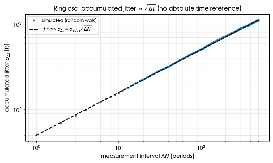
ring 是 free-running、無絕對時間參考,每級 transition 加一點獨立 timing noise,edge 時間做
random walk(隨機漫步) ,累積 jitter 隨量測區間平方根成長([P2] Eq.(8), p.792;κ 由 Eq.(12), p.793):
σ Δ ϕ = κ Δ t \sigma_{\Delta\phi}=\kappa\sqrt{\Delta t} σ Δ ϕ = κ Δ t
這是相位 jitter(無因次) :依 [P2] Eq.(11) σ Δ ϕ 2 = Γ r m s 2 i n 2 ‾ / Δ f 2 q m a x 2 Δ t \sigma_{\Delta\phi}^2=\dfrac{\Gamma_{rms}^2\,\overline{i_n^2}/\Delta f}{2q_{max}^2}\,\Delta t σ Δ ϕ 2 = 2 q ma x 2 Γ r m s 2 i n 2 /Δ f Δ t κ Δ t \kappa\sqrt{\Delta t} κ Δ t σ Δ ϕ \sigma_{\Delta\phi} σ Δ ϕ 時間 jitter 再經 [P2] Eq.(10) 的相位→時間換算 σ Δ t = σ Δ ϕ / ω 0 \sigma_{\Delta t}=\sigma_{\Delta\phi}/\omega_0 σ Δ t = σ Δ ϕ / ω 0 ω 0 \omega_0 ω 0 不在 κ \kappa κ 單位檢查 :κ \kappa κ 1 / s 1/\sqrt{\text{s}} 1/ s i n 2 ‾ / Δ f \overline{i_n^2}/\Delta f i n 2 /Δ f [ A 2 ⋅ s ] [\text{A}^2\!\cdot\!\text{s}] [ A 2 ⋅ s ] q m a x q_{max} q ma x [ A ⋅ s ] [\text{A}\!\cdot\!\text{s}] [ A ⋅ s ] κ Δ t = [ 1 / s ] ⋅ [ s ] = \kappa\sqrt{\Delta t}=[1/\sqrt{\text{s}}]\cdot[\sqrt{\text{s}}]= κ Δ t = [ 1/ s ] ⋅ [ s ] = ω 0 \omega_0 ω 0 [ 1 / s ] [1/\text{s}] [ 1/ s ] σ Δ t = [ s ] \sigma_{\Delta t}=[\text{s}] σ Δ t = [ s ] κ 2 ∝ Γ r m s 2 / q m a x 2 ⋅ i n 2 ‾ / Δ f \kappa^2\propto\Gamma_{rms}^2/q_{max}^2\cdot\overline{i_n^2}/\Delta f κ 2 ∝ Γ r m s 2 / q ma x 2 ⋅ i n 2 /Δ f κ = ( Γ r m s / q m a x ) ( i n 2 ‾ / Δ f ) / 2 \kappa=(\Gamma_{rms}/q_{max})\sqrt{(\overline{i_n^2}/\Delta f)/2} κ = ( Γ r m s / q ma x ) ( i n 2 /Δ f ) /2 ω 0 \omega_0 ω 0 LC 因高 Q Q Q κ \kappa κ 只要是 free-running,兩者長期都會漂 ——
要鎖住絕對時間得靠 PLL/CDR(見 serdes_clocking_connection )。
下圖是 ring edge 時間的 random walk 蒙地卡羅:rms 累積 jitter 對量測 lag 在 log–log 上是斜率 1/2 的直線:
toy 參數:f 0 = 5 f_0=5 f 0 = 5 σ e d g e = 50 \sigma_{edge}=50 σ e d g e = 50 simulations/lab_03_ring_toy_model.py(fig_accumulation)。
第 4 步:ISF 看得見什麼、看不見什麼
看得見(ISF 框架擅長) 看不見/需另外處理 相位敏感度隨注入相位的分佈(Γ \Gamma Γ tank Q Q Q white→1/f²、flicker→1/f³ 的 scaling 強非線性、AM–PM 大訊號效應(一階 ISF 不足) 對稱性→c 0 c_0 c 0 supply/substrate 耦合([P2] 另段定性處理) Γ r m s \Gamma_{rms} Γ r m s q m a x q_{max} q ma x 真實 Γ \Gamma Γ 累積 jitter random walk 確切 κ \kappa κ
design knobs(LC vs ring 對照)
目標 LC knob Ring knob 降 phase noise(1/f²) 提高 tank Q Q Q q m a x q_{max} q ma x 加大每級電流/swing;single-ended:N N N N N N 降 1/f³(close-in) 對稱 differential、低 c 0 c_0 c 0 對稱負載([P2] Fig. 17 symmetry voltage) 寬調諧 varactor(範圍窄) 改 bias 電流/τ D \tau_D τ D 多相位輸出 需額外電路 天生 N N N 小面積 大(spiral inductor) 小(ring 強項)
Worked examples 數值例題
以下兩題用 [P2] 的 ring 白噪 FOM 算具體 L \mathcal{L} L f 0 f_0 f 0 N N N η ≈ 1 \eta\approx1 η ≈ 1 8 / ( 3 η ) 8/(3\eta) 8/ ( 3 η ) γ = 2 / 3 \gamma=2/3 γ = 2/3 V c h a r = Δ V / γ V_{char}=\Delta V/\gamma V c ha r = Δ V / γ V D D / V c h a r = 3 V_{DD}/V_{char}=3 V D D / V c ha r = 3
例 1(用 ring FOM 算 1/f² phase noise,並比較 N=3/5/15)
取 f 0 = 5 f_0=5 f 0 = 5 Δ f = 1 \Delta f=1 Δ f = 1 k T = 4.0 × 10 − 21 kT=4.0\times10^{-21} k T = 4.0 × 1 0 − 21 P = 1 P=1 P = 1 η ≈ 1 \eta\approx1 η ≈ 1 γ = 2 / 3 \gamma=2/3 γ = 2/3 V D D / V c h a r = 3 V_{DD}/V_{char}=3 V D D / V c ha r = 3 L ∣ 1 / f 2 \mathcal{L}|_{1/f^2} L ∣ 1/ f 2 N N N 不顯式出現
(已被 N-independence 吸收),所以 N=3/5/15 給同一個值 。
逐步代入(帶單位) ,用 L ∣ 1 / f 2 = 8 3 η k T P V D D V c h a r ( f 0 Δ f ) 2 \mathcal{L}|_{1/f^2}=\dfrac{8}{3\eta}\dfrac{kT}{P}\dfrac{V_{DD}}{V_{char}}\Big(\dfrac{f_0}{\Delta f}\Big)^2 L ∣ 1/ f 2 = 3 η 8 P k T V c ha r V D D ( Δ f f 0 ) 2
f 0 Δ f = 5 × 10 9 1 × 10 6 = 5000 , ( f 0 Δ f ) 2 = 2.5 × 10 7 , k T P = 4.0 × 10 − 21 J 1 × 10 − 3 W = 4.0 × 10 − 18 s , 8 3 η = 8 3 ≈ 2.667 ( η ≈ 1 ) , V D D V c h a r = 3 , 括號 = 2.667 × 3 × ( 4.0 × 10 − 18 ) × ( 2.5 × 10 7 ) = 8.0 × ( 4.0 × 10 − 18 ) × ( 2.5 × 10 7 ) = 8.0 × 10 − 10 , L ∣ 1 / f 2 = 10 log 10 ( 8.0 × 10 − 10 ) = − 91.0 dBc/Hz . \begin{aligned}
\frac{f_0}{\Delta f}&=\frac{5\times10^9}{1\times10^6}=5000,\quad \left(\frac{f_0}{\Delta f}\right)^2=2.5\times10^{7}, \\[4pt]
\frac{kT}{P}&=\frac{4.0\times10^{-21}\ \text{J}}{1\times10^{-3}\ \text{W}}=4.0\times10^{-18}\ \text{s}, \\[4pt]
\frac{8}{3\eta}&=\frac{8}{3}\approx2.667\quad(\eta\approx1),\qquad \frac{V_{DD}}{V_{char}}=3, \\[4pt]
\text{括號}&=2.667\times3\times(4.0\times10^{-18})\times(2.5\times10^{7})=8.0\times(4.0\times10^{-18})\times(2.5\times10^{7})=8.0\times10^{-10}, \\[4pt]
\mathcal{L}|_{1/f^2}&=10\log_{10}(8.0\times10^{-10})=-91.0\ \text{dBc/Hz}.
\end{aligned} Δ f f 0 P k T 3 η 8 括號 L ∣ 1/ f 2 = 1 × 1 0 6 5 × 1 0 9 = 5000 , ( Δ f f 0 ) 2 = 2.5 × 1 0 7 , = 1 × 1 0 − 3 W 4.0 × 1 0 − 21 J = 4.0 × 1 0 − 18 s , = 3 8 ≈ 2.667 ( η ≈ 1 ) , V c ha r V D D = 3 , = 2.667 × 3 × ( 4.0 × 1 0 − 18 ) × ( 2.5 × 1 0 7 ) = 8.0 × ( 4.0 × 1 0 − 18 ) × ( 2.5 × 1 0 7 ) = 8.0 × 1 0 − 10 , = 10 log 10 ( 8.0 × 1 0 − 10 ) = − 91.0 dBc/Hz .
結果 :L ∣ 1 / f 2 ≈ − 91.0 \mathcal{L}|_{1/f^2}\approx-91.0 L ∣ 1/ f 2 ≈ − 91.0 N=3、N=5、N=15 完全相同 ,
因為固定 f 0 f_0 f 0 P P P N N N − 148 -148 − 148 ∼ 57 \sim57 ∼ 57 Q Q Q q m a x q_{max} q ma x Dimension check :[ J ] [ W ] ⋅ ( 無因次 ) 2 = [ J ] [ J/s ] = [ s ] \dfrac{[\text{J}]}{[\text{W}]}\cdot(\text{無因次})^2=\dfrac{[\text{J}]}{[\text{J/s}]}=[\text{s}] [ W ] [ J ] ⋅ ( 無因次 ) 2 = [ J/s ] [ J ] = [ s ] 1 / Δ ω 2 1/\Delta\omega^2 1/Δ ω 2 ( ω 0 / Δ ω ) 2 (\omega_0/\Delta\omega)^2 ( ω 0 /Δ ω ) 2 10 log 10 10\log_{10} 10 log 10 一行 Python 驗證 :
import numpy as np
def L_ring_fom ( kT , P , f0 , df , eta = 1.0 , vdd_vchar = 3.0 ) :
return 10 * np . log10 ( 8 / ( 3 * eta ) * ( kT / P ) * vdd_vchar * ( f0 / df ) ** 2 )
vals = { N : L_ring_fom ( 4.0e-21 , 1e-3 , 5e9 , 1e6 ) for N in ( 3 , 5 , 15 ) }
print ( { N : round ( v , 1 ) for N , v in vals . items ( ) } )
N-independence 在這裡是「Eq.(23) 裡根本沒有 N N N Γ r m s 2 ∝ N − 3 \Gamma_{rms}^2\propto N^{-3} Γ r m s 2 ∝ N − 3 q m a x ∝ N − 1 q_{max}\propto N^{-1} q ma x ∝ N − 1 P P P f 0 f_0 f 0 × N \times N × N Γ r m s 2 / q m a x 2 ⋅ N ∝ N − 3 + 2 + 1 = N 0 \Gamma_{rms}^2/q_{max}^2\cdot N\propto N^{-3+2+1}=N^0 Γ r m s 2 / q ma x 2 ⋅ N ∝ N − 3 + 2 + 1 = N 0 lab_17 )。
例 2(LC vs ring:同數量級條件下 LC 好多少?)
用 [P1] Eq.(21) 算一個代表性 LC 數字,和上面 ring 的 − 91.0 -91.0 − 91.0 Γ r m s = 0.5 \Gamma_{rms}=0.5 Γ r m s = 0.5 q m a x = 1 q_{max}=1 q ma x = 1 S i = i n 2 ‾ / Δ f = 10 − 24 S_i=\overline{i_n^2}/\Delta f=10^{-24} S i = i n 2 /Δ f = 1 0 − 24 f 0 = 5 f_0=5 f 0 = 5 Δ f = 1 \Delta f=1 Δ f = 1
逐步代入(帶單位) ,用 [P1] Eq.(21) L = 10 log 10 ( Γ r m s 2 q m a x 2 ⋅ S i 4 Δ ω 2 ) \mathcal{L}=10\log_{10}\!\big(\frac{\Gamma_{rms}^2}{q_{max}^2}\cdot\frac{S_i}{4\Delta\omega^2}\big) L = 10 log 10 ( q ma x 2 Γ r m s 2 ⋅ 4Δ ω 2 S i )
Δ ω = 2 π × 10 6 = 6.283 × 10 6 rad/s , Δ ω 2 = 3.948 × 10 13 , 括號 = 0.25 10 − 24 ⋅ 10 − 24 4 × 3.948 × 10 13 = 0.25 1.579 × 10 14 = 1.583 × 10 − 15 , L L C = 10 log 10 ( 1.583 × 10 − 15 ) = − 148.0 dBc/Hz . \begin{aligned}
\Delta\omega&=2\pi\times10^6=6.283\times10^6\ \text{rad/s},\quad \Delta\omega^2=3.948\times10^{13},\\[4pt]
\text{括號}&=\frac{0.25}{10^{-24}}\cdot\frac{10^{-24}}{4\times3.948\times10^{13}}=\frac{0.25}{1.579\times10^{14}}=1.583\times10^{-15},\\[4pt]
\mathcal{L}_{LC}&=10\log_{10}(1.583\times10^{-15})=-148.0\ \text{dBc/Hz}.
\end{aligned} Δ ω 括號 L L C = 2 π × 1 0 6 = 6.283 × 1 0 6 rad/s , Δ ω 2 = 3.948 × 1 0 13 , = 1 0 − 24 0.25 ⋅ 4 × 3.948 × 1 0 13 1 0 − 24 = 1.579 × 1 0 14 0.25 = 1.583 × 1 0 − 15 , = 10 log 10 ( 1.583 × 1 0 − 15 ) = − 148.0 dBc/Hz .
比較 :理想單源下 LC − 148 -148 − 148 − 91 -91 − 91 好 57 dB 。(兩數來自兩篇論文各自的自然參數化:
LC 用 q m a x , Γ r m s , S i q_{max},\Gamma_{rms},S_i q ma x , Γ r m s , S i P , γ , V D D / V c h a r P,\gamma,V_{DD}/V_{char} P , γ , V D D / V c ha r Q Q Q Dimension check :同 [P1] Eq.(21)(見 white_noise_to_phase_noise ),括號無因次 ✓。一行 Python 驗證 :
import numpy as np
def L_lc ( Grms , qmax , Si , f0 , df ) :
dw = 2 * np . pi * df
return 10 * np . log10 ( Grms ** 2 / qmax ** 2 * Si / ( 4 * dw ** 2 ) )
print ( round ( L_lc ( 0.5 , 1e-12 , 1e-24 , 5e9 , 1e6 ) , 1 ) )
以上 [P2] 常數(前置係數 8 / ( 3 η ) 8/(3\eta) 8/ ( 3 η ) Γ r m s = 2 π 2 / ( 3 η 3 ) ⋅ N − 1.5 \Gamma_{rms}=\sqrt{2\pi^2/(3\eta^3)}\cdot N^{-1.5} Γ r m s = 2 π 2 / ( 3 η 3 ) ⋅ N − 1.5 N-independence 這個定性結論 與 N 0 N^0 N 0 simulations/lab_03_ring_toy_model.py。
重點回顧
LC:正弦波形、Γ = − sin \Gamma=-\sin Γ = − sin Q Q Q q m a x q_{max} q ma x
ring:方波、ISF 集中於 transition、無儲能、N N N Γ r m s ∝ N − 3 / 2 \Gamma_{rms}\propto N^{-3/2} Γ r m s ∝ N − 3/2
[P2] 三公式:f 0 = 1 / ( 2 N τ D ) f_0=1/(2N\tau_D) f 0 = 1/ ( 2 N τ D ) Γ r m s ∝ N − 3 / 2 \Gamma_{rms}\propto N^{-3/2} Γ r m s ∝ N − 3/2 8 3 η V D D V c h a r k T P ( ω 0 / Δ ω ) 2 \frac{8}{3\eta}\,\frac{V_{DD}}{V_{char}}\,\frac{kT}{P}(\omega_0/\Delta\omega)^2 3 η 8 V c ha r V D D P k T ( ω 0 /Δ ω ) 2 8 / ( 3 η ) 8/(3\eta) 8/ ( 3 η )
N-independence :固定 f 0 f_0 f 0 N N N N N N N N N 差動 ring 例外 :[P2] Eq.(34), p.796 明含 N N N f 0 f_0 f 0 L \mathcal{L} L 10 log 10 N 10\log_{10}N 10 log 10 N q m a x ∝ 1 / N 2 q_{max}\propto1/N^2 q ma x ∝ 1/ N 2 N = 4 → 12 N=4\to12 N = 4 → 12 + 4.77 +4.77 + 4.77 ISF 看得見相位敏感度分佈與 scaling;看不見絕對 Q Q Q
延伸閱讀