β: This English translation is in beta — the Traditional-Chinese original is the authoritative version.
Jitter and Phase Noise in Ring Oscillators
Prerequisites (recommended reading order): first digest paper_001 (ISF, , the symmetry rule) — every conclusion on this page is [P1]'s ISF applied to the ring. For the time-/frequency-domain language of jitter see psd_phase_noise_jitter.
[P2] applies the ISF framework of [P1] to the ring oscillator. It answers three very practical questions: (1) how does the long-term jitter of a free-running ring grow with time? (2) what effect does the number of stages have on phase noise? (3) why does waveform symmetry suppress close-in noise? The answers are, respectively, , (with "nearly -independent at fixed power and frequency"), and the symmetry experiment of Fig. 17.
Citation
[P2] A. Hajimiri, S. Limotyrakis, and T. H. Lee, "Jitter and Phase Noise in Ring Oscillators," IEEE J. Solid-State Circuits, vol. 34, no. 6, pp. 790–804, Jun. 1999. (file
jitter_ring.pdf, paper_002)
One-sentence contribution
Applying [P1]'s ISF to the ring oscillator yields closed forms for jitter and phase noise, the scaling, and the counter-intuitive conclusion that "at fixed and power, the phase noise/jitter of a single-ended ring is nearly independent of the number of stages " (claim C7, C8).
Why this paper matters
An LC oscillator needs an inductor — large area, hard to integrate; a ring oscillator is all inverters: small area, easy to integrate, wide tuning range — the most common VCO in PLLs/CDRs. But a ring's phase noise is usually much worse than an LC's — [P2] uses the ISF to explain why, and gives actionable design rules:
- It ties the ring's jitter to the same ratio as phase noise (claim C6), unifying "time-domain jitter" and "frequency-domain phase noise" under the ISF framework.
- It settles a commonly misunderstood question: "does adding more stages to a ring make it better?" Under the constraint of fixed power and frequency the answer is "almost no difference" (claim C7) — more stages shrink , but each stage's swing shrinks and there are more devices; the effects cancel.
- It confirms [P1]'s symmetry rule with measurements (Fig. 17): tuning the control voltage to the point of symmetric rise/fall produces a minimum in phase noise (claim C4).
Main assumptions
Per paper_metadata (paper_002.assumptions):
- The same LTV/ISF small-perturbation assumptions as [P1].
- Per-stage device noise is white (plus a 1/f component handled via symmetry).
- Identical stages; delay and noise add independently at every transition.
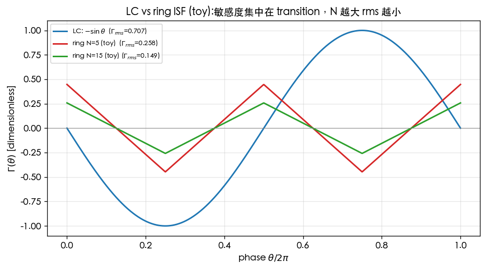
Physical intuition: nearly all of a ring's energy is injected in the instant of a transition (edge flip), so its ISF is not the smooth of an LC but a set of sharp peaks concentrated at the transitions ([P2] Fig. 5). The sensitive spots — where a kick hurts phase the most — sit on those peaks. The more stages, the smaller the fraction of the full period a single transition occupies, and the smaller the rms ISF.
Key equations
Eq.(8): accumulated jitter (the random-walk fingerprint)
Original formula ([P2] Eq.(8), p.792; κ from Eq.(12), p.793):
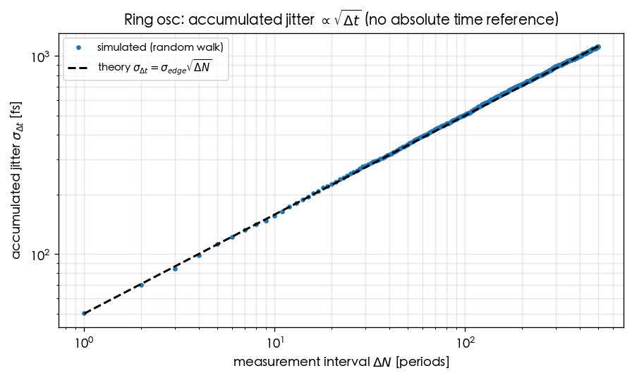
Meaning: for two edges of a free-running oscillator separated by , the standard deviation of the timing error is proportional to — the random-walk fingerprint of an oscillator with "no absolute time reference" (claim C6). is a device-dependent proportionality constant with units of .
Step-by-step derivation: each transition injects an independent, zero-mean timing perturbation with variance . Over there are about transitions; independent quantities add in variance:
Dimension check: is and is ; their product is ✓. Cross-check against [P1] in the frequency domain: corresponds to 1/f² phase noise (the two are the time-/frequency-domain faces of the same thing).
Numerical example: the toy ring sets per-edge fs (see the parameters of
ring_oscillator_timing_noise_accumulation.png). Accumulated jitter over µs (about
5000 periods at GHz): first find . With ps,
,
so . Intuition: the longer the separation, the larger the drift — but it grows only slowly, as .
Python verification:
import numpy as np
from simulations.common.oscillator_models import accumulated_jitter_curve

# toy random walk: each edge adds an independent 50 fs timing perturbation
lags, sigma = accumulated_jitter_curve(f0=5e9, sigma_edge=50e-15, max_lag_periods=500, n_trials=2000)
# expect sigma(lag) ~ sigma_edge * sqrt(lag) -> log-log slope 0.5
slope = np.polyfit(np.log(lags[1:]), np.log(sigma[1:]), 1)[0]
print(round(slope, 2))  # -> 0.50
The full toy derivation is in lab_03_ring_oscillator_toy_model (pedagogical toy model, not transistor-level).
Eq.(11)–(12): the jitter constant κ and its relation to the ISF (verified ✓)
Original formula ([P2] Eq.(11)–(12), p.793, proportionality):
Meaning: the jitter proportionality constant is set by exactly the same ratio as phase noise (claim C6). This ties time-domain jitter and frequency-domain phase noise to the same ISF quantity: the knobs that lower phase noise lower jitter as well.
Verified: [P2] Eq.(12), p.793 gives (verified verbatim against the original PDF rendering); it shares the same ratio with phase noise (claim C6).
Eq.(14): ring frequency vs number of stages
Original formula ([P2] Eq.(14), p.794):
Meaning: an -stage ring with per-stage delay oscillates at this frequency. The factor of 2 comes from the signal having to travel around the ring twice per period (one lap inverts; a second lap returns it in phase) to complete one full cycle.
Dimension check: ✓ ( dimensionless).
Numerical example: for a 5-stage ring at GHz, the per-stage delay is ps. Doubling to while keeping 5 GHz halves the per-stage delay to 10 ps — this is exactly where "at fixed frequency, larger forces faster, smaller-swing stages" comes from, leading into the N-independence below.
Eq.(16): rms-ISF scaling with the number of stages (re-verified in v7 ✓)
Original formula ([P2] Eq.(16), p.794; the radical covers only the constant term):
where is the frequency proportionality constant (Eq.(14)–(15): , ); at , , i.e. , which is the solid line in [P2] Fig. 8 — the radical covers only the constant, and sits outside it.
Meaning: (i.e. ). Intuition: with more stages, each transition occupies a narrower "sensitive window" of the period and the peaks get shorter, so the rms naturally shrinks.
[P2] Eq.(16), p.794 (re-verified in v7: the radical covers only the constant, ; triple-confirmed by the prose's @ and App.B Eq.(55). v3 had misread this as ): three independent lines of evidence — (1) the paper's own text (p.794, the paragraph after Eq.16) states "the dependence of "; (2) the numerical anchor: the text says "solid line = , obtained from (16) for ", and ✓ (if were inside the radical this would give , contradicting the text); (3) independent algebra in App.B Eq.(52)+(54) (p.803): , , which combine to give ; at the bracket equals 1, so ✓. All three point to ; there is no real "formula-vs-text" inconsistency — it was a prior misreading of the radical's scope.
Eq.(23): ring white-noise phase-noise FOM and N-independence (prefactor corrected to 8/(3η) and verified)
Original formula ([P2] Eq.(23), p.796; the lower bound is Eq.(25)):
where is the MOSFET channel thermal-noise coefficient ( long-channel, larger for short-channel), is the device's characteristic voltage (long-channel ), is the power dissipation (Eq.(21): ), and the per-stage noise is given by Eq.(17),(18) .
Meaning: ring white-noise phase noise collapses into a figure of merit — only , the voltage ratio , and appear. Key conclusion (claim C7): is entirely absent from Eq.(23) — at fixed and power , the phase noise of a single-ended ring is independent of the number of stages .
Why N-independent: microscopically, raising lowers (Eq.16) but simultaneously lowers each stage's swing and adds more noisy stages; [P2] shows these effects cancel exactly at fixed , , so Eq.(23) contains no . Hence "how many stages should my ring have" is not decided by phase noise, but by phase margin, tuning range, area, quadrature needs, and other considerations.
Correction note (v3): the prefactor of [P2] Eq.(23) is ( being the stage-delay proportionality constant of Eq.14, ); enters only through . (v2 mistakenly changed it to and mislabeled it "verified verbatim"; v3 corrected it against the original PDF p.796.) The lower bound is accordingly corrected to . (noise coefficient) and (frequency proportionality constant, Eq.14) are different quantities — do not confuse them.
Eq.(31)–(35): differential-ring phase noise — with an explicit (verified ✓)
Original formulas ([P2] Sec. V-B, p.796, verified verbatim against a render of the original PDF):
Power (Eq.(31)) and frequency (Eq.(32)):
Noise on each single-ended node (Eq.(33); two shares — differential transistor + load resistor — with for a balanced long-channel stage, short-channel):
The ring has nodes (two outputs per stage), and the total phase noise is times the single-source value (p.796, verbatim: "The phase noise and jitter due to all noise sources is times the value given by (6) and (12)." — this 2 is a node count, not the SSB convention's 2). Combined with the of Eq.(16), it collapses into (Eq.(34)/(35); is the paper's ):
The paper states verbatim that both are "valid in both long- and short-channel regimes of operation with the right choice of "; a bipolar differential ring's shot + load noise (Eq.(36), p.797) folds back into the same two equations with .
Meaning: only two differences from single-ended Eq.(23) — an explicit , and an extra load share in the bracket. At fixed and , a differential ring's phase noise degrades with (; for jitter, ) — the lost other half of N-independence.
Why the appears (exponent bookkeeping, fixed , , fixed swing): is a static bookkeeping (unlike Eq.(21), it is not tied to ), so fixed forces ; Eq.(32) then forces (p.797, verbatim: "…reduce the swing, and hence , by a factor of "). Hence . Full term-by-term table and worked example: lc_vs_ring Step 2b.
[P2]'s conclusion sentence (pp.796–797, verbatim): "Note that, in contrast with the single-ended ring oscillator, a differential oscillator does exhibit a phase noise and jitter dependency on the number of stages, with the phase noise degrading as the number of stages increases for a given frequency and power dissipation."
Numerical example: GHz, MHz, J, mW, , , (fixed swing): gives dBc/Hz, gives dBc/Hz, dB; and grows by . (The absolute values inherit [P2]'s SSB bookkeeping, the same family as the 4 in the denominator of [P1] Eq.(21); the time-domain convention shifts everything by dB. is a difference, identical under both conventions.)
Python verification:
import numpy as np
def L_ring_diff(N, kT, P, f0, df, eta=1.0, vdd_vchar=3.0, vdd_swing=2.0):  # [P2] Eq.(34)
    return 10*np.log10(8/(3*eta) * N * (kT/P) * (vdd_vchar + vdd_swing) * (f0/df)**2)
L4  = L_ring_diff(4,  4.0e-21, 1e-3, 5e9, 1e6)
L12 = L_ring_diff(12, 4.0e-21, 1e-3, 5e9, 1e6)
print(round(L4,1), round(L12,1), round(L12-L4,2))   # -> -82.7 -78.0 4.77
One-line design rule: single-ended = -free (Eq.23); differential = fewest stages wins (Eq.34, dB per doubling) — the lower bound on is set by phase margin / quadrature / multiphase needs, so do not add more. Tail-source noise near "surprisingly" does not enter the phase noise (p.796); what enters is its low-frequency noise (the symmetry path) and its noise near even harmonics (filterable with an LC).
Key figures
| Paper figure | Page | Content | Site counterpart | Note |
|---|---|---|---|---|
| Fig. 5 | 793 | Overlaid ISFs at the same frequency for different stage counts (3/5/15) | scaling intuition () | ✓ |
| Fig. 6 | 793 | Approximate waveform and ISF of one single-ended ring stage (energy concentrated at the transition) | toy triangular ISF (lab_03) | ✓ |
| Fig. 8 | 794 | rms ISF vs for rings of different stage counts; the solid line is Eq.(16) at , | scaling argument for lc_vs_ring_isf_comparison.png | ✓ |
| Fig. 9 | 795 | rms ISF vs for differential rings under three constraint scenarios (fixed power/fixed swing, fixed power/fixed , fixed tail current/fixed ) | empirical support that Eq.(16)'s scaling carries over to differential rings (a premise of the Eq.(34) derivation) | ✓ |
| Fig. 17 | 802 | phase noise vs the symmetry (control) voltage, with a minimum at the symmetric point | direct experimental support for the symmetry design rule | ✓ |
Fig. 17 is the smoking gun for the symmetry rule: sweep the control voltage; at the point where the PMOS pull-up current = NMOS pull-down current and the waveform is symmetric, is squeezed to its minimum, 1/f³ upconversion is suppressed, and the phase noise shows a bowl bottom. This directly verifies [P1] Eq.(24) (claim C4).
This site compares LC () and ring (triangular ISF, peaks shrinking with ) with a toy model — not transistor-level:
Design insights
- Jitter and phase noise share one origin: lowering lowers both; do not treat long-term jitter and close-in phase noise as two separate problems.
- Adding stages is not a phase-noise cure: for single-ended rings at fixed , the phase noise is nearly independent of (conclusion verified); differential rings want even fewer stages — Eq.(34) contains an explicit , costing dB per doubling at fixed , . The real reasons to add stages are quadrature/multi-phase outputs, tuning range, and phase margin.
- Symmetry is the master knob for close-in noise: tune the rise/fall to be symmetric (e.g. the control voltage of Fig. 17) to suppress and push the 1/f³ corner far out. Differential rings are usually more symmetric than single-ended ones.
- The steeper the transition, the better: the energy is concentrated at the transitions; the higher the slope, the larger and the relatively smaller .
Design-side summaries in lc_vs_ring and symmetry; the SerDes view is in serdes_clocking_connection.
Limitations
Per paper_metadata (paper_002.limitations):
- Toy/first-order: short-channel effects and detailed device noise are approximate.
- The N-independence conclusion holds only for single-ended rings, at fixed power, fixed frequency, and for the specific noise model ([P2] Sec.V, Eq.(23)/(25), p.796, verified, claim C7); a differential ring instead contains an explicit (Eq.(34), p.796, verified).
- Substrate/supply noise is treated separately and qualitatively.
Relationship to other papers
- [P1] is the foundation: this page's jitter , , and symmetry all use [P1]'s ISF and Eq.(21)/(24).
- [P3]/[P4] also use the ring as a vehicle ([P4]'s ILFD/prescaler is an inverter-chain ring), extending the ISF from phase noise to injection.
- [P5] is unrelated to this page; but latch-based/differential ring start-up also relies on cross-coupled positive feedback (the corner-case bridge of claim C12).
Further reading / companion teaching pages
| Which block of this page | Companion teaching page | What that page adds |
|---|---|---|
| The LC () vs ring (transition-concentrated) ISF comparison and the N-scaling argument | lc_vs_ring | The , , and phase-noise trade-offs of the two topologies organized into a design table |
| The random walk behind Eq.(8) accumulated jitter | lab_03_ring_oscillator_toy_model | A runnable toy model: add an independent perturbation per edge; the log-log slope verifies (pedagogical toy, not transistor-level) |
| The Fig. 17 phase-noise bowl at the symmetric point, , and the 1/f³ corner | symmetry | how rise/fall symmetry suppresses , differential vs single-ended, design knobs |
How to read: this page is the story of "how the paper applies [P1] to the ring"; to watch jitter grow as hands-on, go back to lab_03; to turn the conclusions into topology selection, go back to lc_vs_ring and symmetry. For the SerDes view see also serdes_clocking_connection.
What to remember
- Accumulated jitter : the random-walk fingerprint of a free-running oscillator ([P2] Eq.(8), p.792).
- is set by the same as phase noise ([P2] Eq.16/23, verified).
- ([P2] Eq.(16), p.794, re-verified in v7: the radical covers only the constant, triple-confirmed by the prose's @ and App.B Eq.(55)); yet at fixed , the phase noise is nearly independent of (no in [P2] Eq.(23), claim C7, verified).
- Differential rings are the opposite: [P2] Eq.(34), p.796 contains an explicit (, verbatim on p.797); at fixed , the phase noise degrades as ( costs dB); differential designs use the fewest necessary stages.
- Fig. 17: the phase-noise bowl bottom at the symmetric point — the smoking gun for the symmetry rule (claim C4).
- Rings integrate better than LC but usually have worse phase noise; this page shows where the knobs are.